Despite the low cost the 2J1 wideband offers functionality only usually found on much more expensive systems. The base package includes the latest Bosch 7200 sensor. You may like to consider the LA1 or LX1 display for use with the 2J1.
The various I/O connections are described below. The connection diagram are to the right, along with wire colours to aid you in connecting the 2J1 to your vehicle. Just remember not to short out any of the unused wires against battery voltage or GND.

On the top of the case (with the sticker) can be found ..
- Status LED - Displays information about sensor function, and indicates errors and alarm conditions.
- CAL Button - When held down, initiates the Auto-cal sequence (indicated by a series of sharp flashes on the status LED) .
The ends of the case carry the sensor cable, the power cable, the display/RS232 cable and I/O cable.
- Sensor Cable - this is a permanently connected flexible fibreglass sheathed cable brought out via a rubber grommet, with a connector for low cost Bosch LSU 4.2 sensor (UEGO sensor are not supported).
- Power Cable - is normally wired to the vehicle's power via a high current (5 Amp) in-line fuse and then to a switched power point. Power is normally made available when the ignition is switched to ON. We discourage temporary installations using a cigarette lighter because the sensors should always be powered when exposed to exhaust gasses.
- Display Cable - the display cable replicates the standard RJ45 socket found on other Tech Edge wideband units, and provides ground, RS232 communications, and current limited power for a Tech Edge display such as LD02 or LA1.
The larger grey cable is referred to as the I/O cable, and carries various inputs and outputs described below.
- BLACK
|
GROUND - Provides a ground return for Vbatt, and a ground reference for NBsim, WBlin-, etc. Also internally connected to the SHIELD wire. |
- BROWN
|
USR 1 - A 0-5v Analog channel for logging sensors such as MAP & TPS. |
- RED
|
USR 2 - As per USR 2, values appear in the RS232 frame generated by the 2J1 unit. |
- ORANGE
|
LSS Tx - An optional Low Speed Serial output (1200 baud), for connection to a future intelligent display, not currently activated in firmware. |
- YELLOW
|
Vbatt - Provides battery voltage to remote 12 volt sensors or displays. |
- GREEN
|
WBlin- - Ground reference for WBlin+, should be tied to GND or close to GND as it affects WBlin+ if left floating. |
- BLUE
|
WBlin+ - 10bit PWM-sourced Differential Wideband output. |
- VIOLET
|
NBsim - 10bit PWM-sourced programmable output, used for Narrowband sensor simulation. |
- PINK
|
RPM - 12 volt compatible (COIL style) RPM pickup for logging engine revolutions. |
- WHITE
|
PULSE - 5 volt PULSE input for logging an additional pulse input, intended for Vehicle Speed Sensors. |
Wideband output
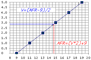
The wideband output voltage can be configured using the config utility, the default setup is shown in the graph below.

Simulated narrowband output
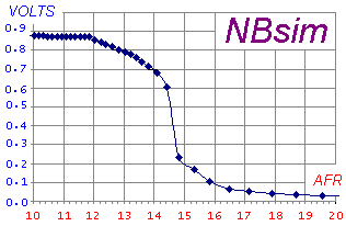
Just like the wideband output the simulated narrowband output can be configured to suit your ECU.
